D8233 Vacuum System Restoration 06-14 October 2012
Saturday 6th October 2012 Attendance: 3 Today marked the beginning of the effort to restore the 2” Vacuum Brake pipe system to D8233, Jason arrived early and after some breakfast went up to the storage unit in his Hatchback car to collect all the parts of the Vac kit that had been stored there, on the way he dropped into Castlecroft yard and bumped into Dave Pendleton who followed Jason up to the storage unit where he helped Jason dig out the various pipes, valves & fittings that make up the Vac kit load them into the car then drove the short distance down to Baron Street where they found Phil Cribbin waiting for them so after a quick brew they went down to the Workshop container and unloaded all the Vac kit out of the car then began the task of dismantling the pipes first removing the old vac bags, Phil & Dave had started unscrewing some of the pipe fittings, they swapped the work bench vice for the pipe vice and that helped them grip the pipes properly while they were being undone, Phil, Dave & Jason took it in turns to unscrew the pipe & fittings, After lunch all three were back on the job and made light work of the majority of the pipe assemblies they had to strip down and by mid afternoon, all the pipe & fittings had been stripped down and neatly laid out on the floor, Jason then asked if Phil & Dave could help him remove the R/H exhauster pannier on the Loco, So they set about unbolting the, it was not long before the pannier was it had gone very well today and tomorrow Jason & Phil would begin the task of drelling & cleaning up all the pipes & fittings. Sunday 7th October 2012 Attendance: 2 Today the agenda was to drell all the pipes & fittings back to bare metal, Jason got together all the tools he would need for the job while fetching it Phil Cribbin texted to say he was on site and when he arrived they had a quick cuppa before heading down to the container, After setting up, Jason went through the vac kit and sorted out all the fittings required then Phil & Jason started the drelling marathon with the Female elbows, Phil had set himself up on the work bench vice while Jason used the pipe vice on the floor facing out of the container door, soon both the angle grinders were in full swing drelling off pipe fittings and the work continued at a sedate pace, At lunch time they both stopped for a break, after lunch the job continued, there was a lot of the small threaded pipes to get through these took up the majority of the work load, cleaning out the threads proved to be time consuming due to the amount of old PTFE tape and jointing compound that had congealed itself between the threads and set hard, by 4 pm Phil had to depart, so Jason soldiered on, there was still a number of the larger pipes to do as well as the original D8233 pipes that had been removed from the cab, it would be dark by the time Jason had finished at 8:15. Monday 8th October 2012 Attendance: 2 Today it would not be until 11 am before Jason begin work Jason began by cleaning up the container from the previous evening drelling session, today Jason concentrated on making sure that the pipes and fittings were all clean on the inside, for this task he used the drills with a variety of small drelling cups & wheels that would fit inside the 2” pipes, starting with the Female elbows he clamped then in the vice and ran the drill around the inside of the threads with a small wire wheel, he continued working his way through the pipe fittings until he stopped for lunch at 1 pm, during lunch Phil Cribbin arrived up and joined Jason down at the container, the pipe vice was repositioned to allow both Jason & Phil to work side by side at the same time, they had to swap drills often as the two different types of wire wheels were fitted to each drill and they were best suited to different tasks, soon the pair got into a rhythm and made steady progress, when the fitting were all clean they moved onto the pipes, On some of the flange fittings, Jason used the 2” BSP tap to run through the treads, later he would use the 2” BSP tap & die set to run through all the threads on the pipes thus smoothing out any rough spots on the threads, at 4:30 pm Phil had to depart so Jason had a tea break before going back to the container to finish of the re-threading, when all was done he sorted the pipes into two piles, of single & double threaded pipes, lastly he got some green anti-corrosive primer paint, and begin the painting process on the fittings, when this work was finally finished it was gone 8 pm again so Jason called time on another good days work. Tuesday 9th October 2012 Attendance: 1 With the majority of the preparation work on the pipes and fittings now completed Jason could now turn his attention to the cutting and threading stage but before first Jason had to measure all the pipes so that he would know if any of the pipes that he had would be suitable to use as is on the Class 15's Vacuum system, when this was done he laid out a number of buckets, into which he placed the various component parts for each of the seven pipe assemblies that he had listed on the “Cheat Sheets” he had made, Next Jason soon set about rigging up the chop saw and marked up the first pipe to be cut, but this saw struggled to cut the pipe so Jason swapped to using his Electric reciprocating saw, this saw worked much better so the cutting continued for a while until he ran out of single ended pipes to cut, It was about this time that Jason stopped for lunch, after which he sought out Lee Kenny and asked him if he could borrow the carriage works pipe threading machine, to which he agreed, so Jason went to fetch it, next he prepared a number of pipes that needed second threads cutting on, pipe vice and repositioned for use as a solid mounting point for the pipes while the threading machine was used, with the first pipe set up Jason began cutting, he liberally lubricated the cutting head with some special cutting fluid and eventually cut the threads he needed, Wednesday 10th October 2012 Attendance: 1 This morning Jason went down to the container and appraised the situation and what pipes were left that needed threading, he needed some Barrel pipes which are short lengths of pure thread that are used to join two fittings together, at first Jason had some trouble trying to cut the extended threads needed to make barrel pipes and had to go into the Co-Bo tent and drag out the large length of plain 2” pipe, this was secured it in the pipe vice and a length chopped of pipe off using the sabre saw, this was then put in the pipe vice and the pipe threader began to bite into the pipe, soon Jason had enough thread for the barrel pipes, when they were done Jason had completed two more pipe kits for the loco, After dinner Jason decided to attempt to fabricate the components for the “T” section pipe that connects the two exhausters to the train, to make it 45 deg cuts were needed so Jason decided to use the Chop saw again as it had a mitre clamp that could be set for 45 deg, Jason set the saw up for the cut however as before it was struggling to cut through the metal, so Jason packed up the chop saw and used the sabre saw to finish the cut, however as the sabre saw is used free hand and Jason made a mistake in the cutting of the second angle cut all uneven, After this Jason decided to begin refitting pipe work to the loco starting in the cab, after giving the cab a good tidy up soon he was ready to begin pipe fitting, but before that the main manifold was out of position, so Jason had to spend some time twisting it back into its correct orientation, he then began to installing the cross over pipe but found that it came up a little short, so Jason removed it to take back to the coach to check if it was the correct length, next Jason put back the stand pipe for the No1 end driver train brake handle, but found tightening some of the large union joints difficult as he didn’t have big enough spanners however by this time the workshop was closing up as it was 4:30 pm, Jason had to leave the loco else he would get locked in, so he returned to the coach, where Jason prepared the top pipe of the “T” section pipe and got the welder out to weld them together, due to the uneven angular cut there were gaps that Jason had to fill with specially cut metal inserts, Jason then smoothed the joins with weld, the end result isn't pretty but hopefully it will work? Thursday 11th October 2012 Attendance: 1 After the morning ritual of going up town for his Breakfast, Jason stopped by Castlcroft to see if he could find a large spanner to fit the 2” union joint in the tool store there, but he was unsuccessful so returning to the workshop container and bought the welded “T” pipe down for some fettling, Jason clamped the “T” pipe in the vice and proceeded to grind all the knobbly welds smooth, he then fitted three blanking caps to the pipe ends ready for pressure testing it later, Next it was onto the main event, assembling the pipe work, Jason started with the parts for “Cheat Sheet” #1 this is the output pipe from the R/H exhauster, using PTFE tape on the threads, he gradually threaded all the parts of the pipe assembly together and soon the first pipe assembly was complete, the next pipe assembly “Cheat Sheet” 5 (output for the L/H exhauster) was also quickly pieced together, with the first two pipes ready to go, Jason took them and the blanked off “T” pipe back to the coach for dropping off in the work shop, then Jason went into the works with the first two pipes eager to install them, On arriving at the loco he found the exhausters flanges had not been cleaned off, so Jason had to fetch a drill with a drelling wheel to dress the flanges, he also removed the old nuts and took them back to the coach for cleaning up, when that was all done Jason attempted to fit the first pipe (SC#5) onto the L/H exhauster one of the down pipes was too long by ½” and this caused the lower cross pipe to foul the Exhauster Oil filter, so he removed the pipe again, took it to the container, removed the offending pipe and substituted it for one that was slightly shorter, on getting back to the loco the now shortened pipe cleared OK, then Jason checked the length of the down pipe to the floor mounted stand pipe and found it too long, so the new stand pipe (yet to be welded to the floor had to be trimmed a little before the clearances were OK. Next it was onto the R/H exhauster output pipe (CS#1) again he had to drell the pipe flanges and the mounting nuts and washers and trim the down pipe as it was a tad too long, then as the original silencer connection pipe is still in situ Jason fitted the silicon hose to complete the pipe assembly, Then over to the L/H of the loco again for another of the exhauster pipe (CS#4) the input pipe for the L/H exhauster, The top end of the pipe is mounting to the flange for the Snifter/Strainer Check valve, this was temporally fitted using the bulkhead mounting bracket, from this a 24” Vacuum hose (Or Vac Bag) runs down in an arc to the pipe coming off the Exhauster, a used one would be fitted here for mock up purposes, The Exhauster pipe was found to have some minor clearance issues as it fouled the pannier mounting frame when fitted as the plans dictate, however it can be skewed slightly to one side to clear the obstruction, By now the steam works were locking up so Jason returned to the support coach, here he set up the air compressor with an airline and compressed air blower, he then ran a bucket of water into which he plunged the “T” pipe top end first, he then pushed the air blower into the small hole he had drilled in the third blanking cab and a swarm of bubbles erupted from all manner of places around the welded joint on the “T” pipe, this was a leak test and obviously it failed miserably, So Jason had to re-weld the “T” joint on the pipe and retest for leaks each time, this took at least three beads of fortified welds on each side of the “T” joint, eventually though the leaks subsided and the “T” pipe was complete, Jason took it back down to the container where he removed the blanking caps and applied the snifter flanges and elbows to form the pipe assembly for “Cheat Sheet” No 3, when that was done he primer painted all the bare metal parts, and after a quick sweep up he loaded all the power tools into the trolley, locked the container and headed back to the coach, before he called time. Friday 12th October 2012 Attendance: 1 Today should have been the final day of the Vac system refit, and the remainder of the outstanding jobs were the ones that Jason had been deliberately putting off as he knew that they would awkward and time consuming, but this morning he had reached a point where he could not make any further progress without tackling some of these difficult tasks as they are all crucial to the arrangement and integrity of the vacuum system, So Jason had to bite the bullet and choose a job to be getting on with and that would be the fabrication of the bulkhead mounting brackets, these are made from ¼” steel plate, and have 90 deg bends in them to form an “L” shape and they have many large bolt & pipe holes in them, all four brackets go with CS#3 that is the central section where all the large valve gear for the Vac system is fitted, all these valves are quite large and weighty so the brackets that hold them on the cab bulkhead will also be suitably chunky hence the reason for the ¼” plate, so Jason managed to find some off cuts of plate that were lying around that he could make the brackets from, but first the rusty plates had to be cleaned up so he got out the drelling gear and did just that, after cleaning the first plate was then marked with the outline of one of the snifter brackets, Jason utilised the Plasma cutter to cut out the basic triangular shape of the brackets and soon two bracket “Blanks” had been successfully cut and a small amount of edge dressing was required with an angle grinder, then Jason marked out the larger “D” shaped brackets for the Cut Off valve mountings, however the Plasma Cutter was unable to penetrate this second plate, it is suspected that it is made from a different higher grade of steel, so instead Jason had to use cutting wheels on angle grinders to cut through the thick plate eventually the basic shape of the bracket was formed so Jason stopped for lunch. After lunch Jason began drilling the holes in the brackets using the pillar drill, he drilled some small pilot holes first then moved onto widening the holes with the full sized drill bit, The Snifter brackets were drilled first then the “D” brackets were done, while drilling copious amounts of lubricant was sprayed on the drill while it was cutting, after cutting the snifter holes Jason test fitted the snifter flange to maker sure the holes were drilled in the right place, which they did, next Jason got out the hole saw set, at first he using the pillar drill to cut a snifter bracket hole, but that didn't go so well so he instead clamped the work piece in the vice and used the Makita drill, this worked much better and once the holes in both snifter brackets had been cut Jason tested the fit again with a pipe this time and next he polished the plates till they were shiny, after that he did the same to the “D” brackets and once they were done it was off to Buckley wells carriage works to used the bending machine to bend the brackets to finish them off... only to the told that the bending machine won't bend 1/4” plate, so Jason was left with the prospect of cutting and welding the 90 deg bolting tabs instead, So after a quick tidy up in the work shop Jason set to cutting off the bracket tabs and then used the welder to weld then back on, he took great car to make sure that the tabs were at right angles and that the bolt holes were even and lined up properly, once all that was done he tided up the welds, packed the welded away and all the other tools, gave the workshop another quick sweep over and lastly slapped on some green primer paint onto the brackets he had just fashioned, tomorrow Jason would go and enjoy the ELR autumn diesel gala but there are still many vac system jobs left to do. Sunday 14th October 2012 Attendance: 1 On Saturday Jason took the day off and went up to Bolton St station and spend the day riding around on the trains of the ELR's autumn diesel gala, on the Sunday morning he could have gone out on the trains again but as there was unfinished business on the Class 15's vacuum system, he decided that he'd best do a bit more, with the bulkhead mounting brackets completed he could now mount the Pipe work and valves of the “Guts” section between the exhausters, as shown on CS#3, so to start off with Jason took the newly completed brackets round to the loco and tried them on for size to see if the bolt holes lined up properly, but first Jason had to use a tap to clean out the threads on the captive bolt holes, when he test fitted the brackets the top ones for the Snifter mounts lined up OK but the holes were a little tight on the bolts so Jason had to remove them again and relieved the holes by slightly drilling them out, the lower “D” brackets needed the mounting holes drilling out as well to cure a slight alignment issues, once that was done Jason spent some time sorting out and drelling up all the other mounting bolts for the valve flanges, on returning to the loco Jason could now test fit all the brackets and this time they went on OK, Next Jason would have to make a cut out into one of the “D” brackets this was necessary as the Flange pipe was all welded with mounted bosses and could not be dismantled to fit the mounting flange, so after Jason made the first cuts with the hack saw he then had to grind the gap back quite a bit more with the angle grinder before the pipe would finally pass over, next Jason went over to the workshop container and collected up all the pipe assemblies, snifter valves and cut off valve that needed to go with the central pipe assembly, Jason also had to make up a stub pipe for the opposite snifter flange, also the other flange pipe had to be partially dismantled to allow the fitting of the “D” bracket over it, when everything was together Jason put it all in the trolley and carried it around to the loco where he unloaded all the bits onto the sole bar, next he returned to the support coach and drelled up a number of Snifter flange bolts, and he used the Tap set to run through the threads on the mounting nuts as well, Jason then stopped to have some lunch. After lunch, Jason began assembly of the central pipe arrangement, first he loosely fitted the two snifter valve into the bracket on each side then Jason attempted to slot in the “T” pipe section which was not easy given the limited clearance between the cab bulkhead and the drive belts for the overhung exciter sticking out the back of the generator set, however there soon became a problem, the lower “D” bracket was not fitting over the welded flange properly and the central hole was slightly undersized, So Jason had to remove the “T” pipe assembly and “D” bracket again and take it back to the coach, to enlarge the circumference of the central hole, once done the “T” pipe and bracket were again fitted to the loco and this time things started to fall into place, it was rather tricky to slip the snifter gaskets into place wile trying to support the whole assembly, one of the snifter flanges was slightly out of kilter and the “T” pipe had to be removed again for this alignment discrepancy to be corrected, eventually the top section was complete and all bolted up solidly, Next it was onto the lower half of the assembly, and this meant lugging around the extremely heavy and ungainly Vacuum Cut Off valve, Jason attached the valve to the flange that was already fitted, but found the bolts to be a little too short however that is something that would have to be addressed later, once the valve was secured then the opposite flange & bracket were offered up, then another issue came to light, the captive bulkhead holes did not line up with the holes in the bracket, they were about ¾” out, Jason found there to be a number of reasons for this discrepancy but as the R/H side of the pipe assembly all lined up and fitted correctly and the opposite end of the pipe seemed to end in the place it was supposed to then Jason thought it would be easier to relocate the bulkhead captive bolt holes then reposition the valve and pipe properly, but that too would have to wait for another time, It was mid afternoon and Jason was ready to call time on his 8 days working on the vac system, before he left the loco he went around with the green primer paint and touched up a number of pipes that had not been painted yet, then he picked up the tools and returned to the support coach to get ready for going home, it had been a productive week, but Jason was a little disappointed that he did not get everything done that he would have wanted? He had been grateful to the help given to him by Dave Pendleton & Phil Cribben, however the following weekend there was another opportunity to get the vac system finished off. The next working weekend is November 16/17 - If you wish to lend a hand please contact Chris Tatton |
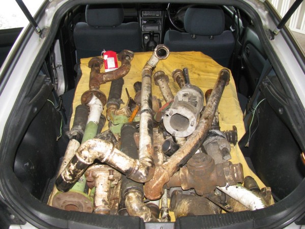 |
| Above : All the Vacuum kit parts are seen loaded into the back of Jasons car for ferrying down to the work shop container. © C15PS |
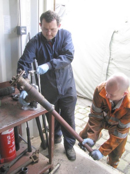 |
| Above : Phil & Dave are busy dismantling one of the original pipe assembles from the vac kit pile. © C15PS |
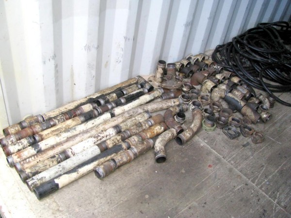 |
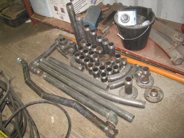
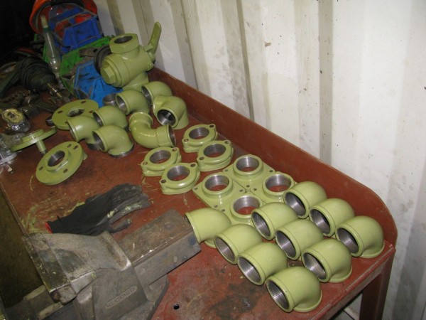
Above : All the pipes and fittings have now been disassembled ready for drelling up the next day. © C15PS |
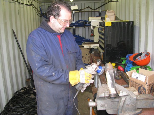 |
Above :
Phil is seen drelling up some of the pipe work that has been secured in the vice
. © C15PS |
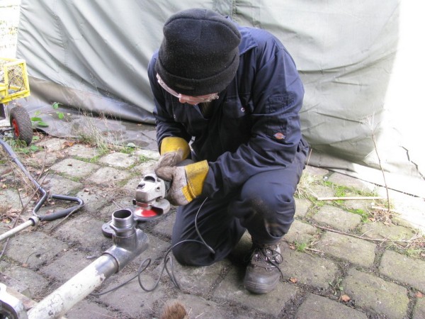 |
| Above : Jason used the pipe vice on the container floor to secure his pipes when he was drelling them up. © C15PS |
 |
| Above : It took all day to get all these pipes drelled back to bare metal. © C15PS |
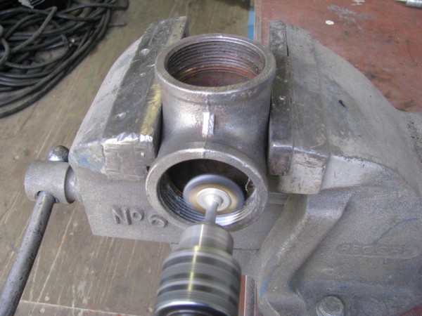 |
| Above : The Drill was used to clean up the threads inside the pipe fittings.© C15PS |
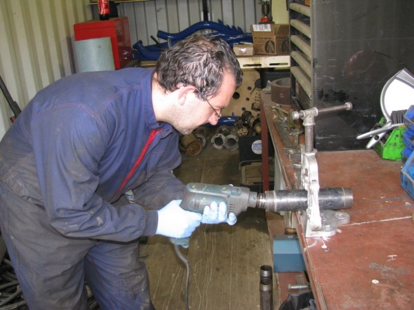 |
| Above : Phil is seen using the drill to clean the insides of one of the pipes clamped in the pipe vice. © C15PS |
 |
| Above : At the end of Day 3 all the flanges and fittings were painted in green primer. © C15PS |
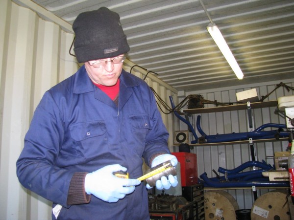 |
| Above : Jason checks the measurement of one of the pipes to see if its suitable length for use on the loco. © C15PS |
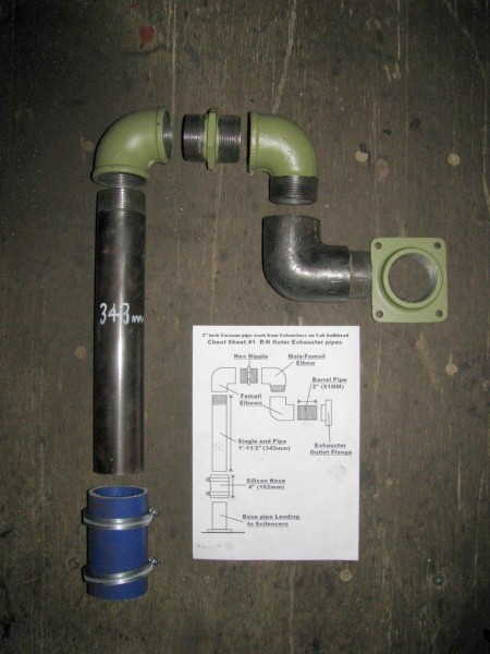 |
| Above : The first of the pipe assembly kit is complete, the Cheat Sheet is shown for comparison. © C15PS |
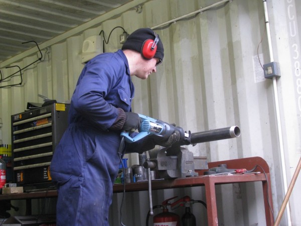 |
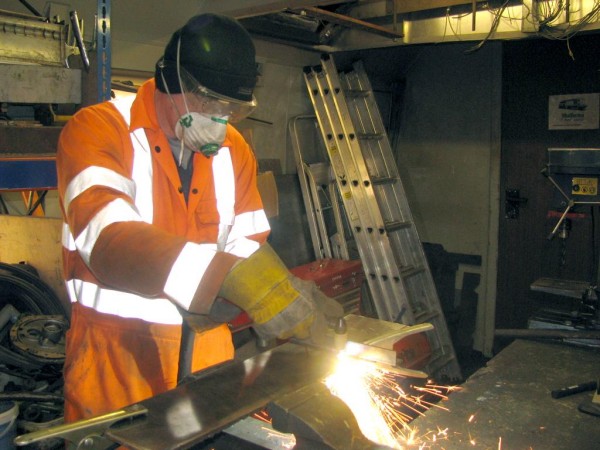
| Above : Jason uses the Sabre saw to cut a piece of pipe to the required length. © C15PS |
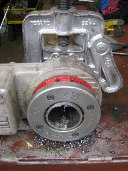 |
| Above : The Pipe threading machine is seen cutting a thread on the end of one of the pipes.© C15PS |
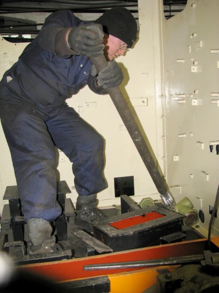 |
| Above : Jason is using some extra leverage to re-position the vac pipe manifold in the cab. © C15PS |
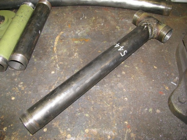 |
| Above : The two pipes that make up the "T" section pipe have now been welded together. © C15PS |
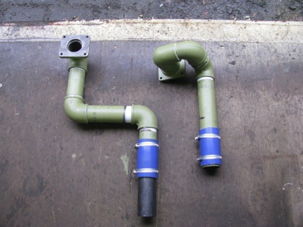 |
| Above : The first two Exhauster pipes have now been assembled and are ready for fitting to the loco.© C15PS |
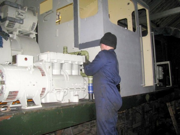 |
| Above : Jason is seen fitting one of the pipe assemblies to the L/H exhauster. © C15PS |
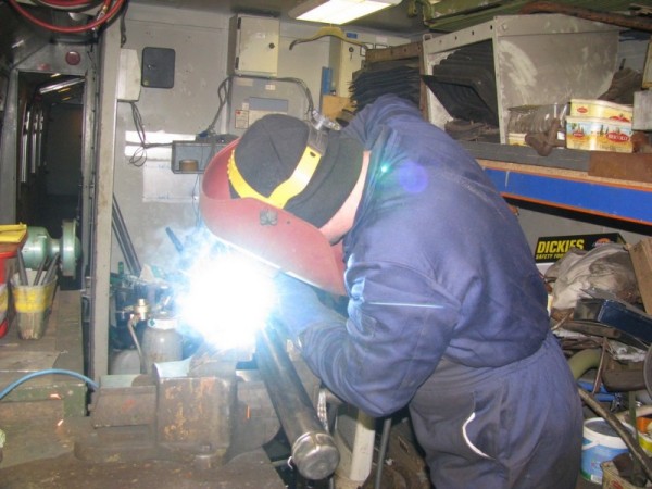 |
| Above : After a failed leak test the "T" section pipe required further fortification welds to be applied. © C15PS |
 |
| Above : After the plate had been cleaned Jason used the Plasma cutter for cutting out the Snifter brackets. © C15PS |
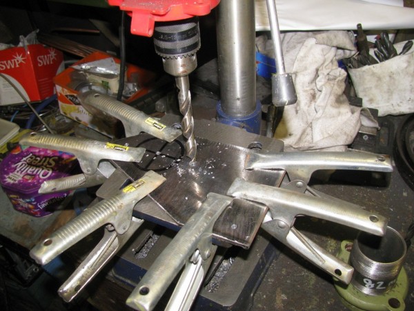 |
| Above : During drilling of the bolt holes the work piece was secured to the drill press using spring clamps. © C15PS |
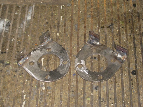 |
| Above : Fabrication of the "D" shaped brackets has now been completed. © C15PS |
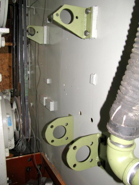 |
| Above : The finished brackets were test fitted to the cab bulkhead to make sure they lined up OK. © C15PS |
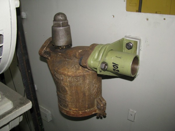 |
| Above : The first Snifter valve is mock fitted to the L/H mounting bracket. © C15PS |
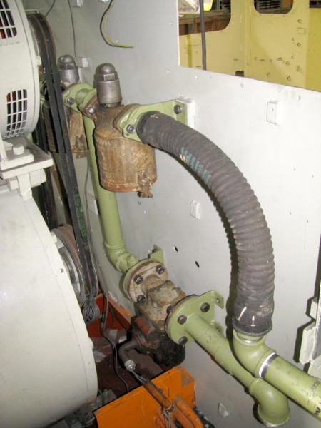 |
| Above : The assembly of the central valve section has now been fitted to the cab bulkhead. © C15PS |
Fancy Getting Involved? click on the You Can Help page